Wondering how much hiring an architect cost? Discover architect prices, cost factors, and money-saving tips to help you plan your home project with confidence.
You can draw up this guide in a pinch


A blueprint is a two-dimensional drawing of a three-dimensional building.
Reading a blueprint requires learning and then breaking down each part.
When in doubt, ask a pro for help.
If you were involved in every step of designing your floor plan, pouring that same level of care over your blueprint would only feel natural. But one glance will tell you that learning how to read blueprints isn’t as straightforward as it seems. You won’t need to know every detail; understanding what you’re looking at can let you have an active, informed role in your construction project. In this guide, we’ll cover what a blueprint is, break down each part, and give you a step-by-step guide on how to read one.
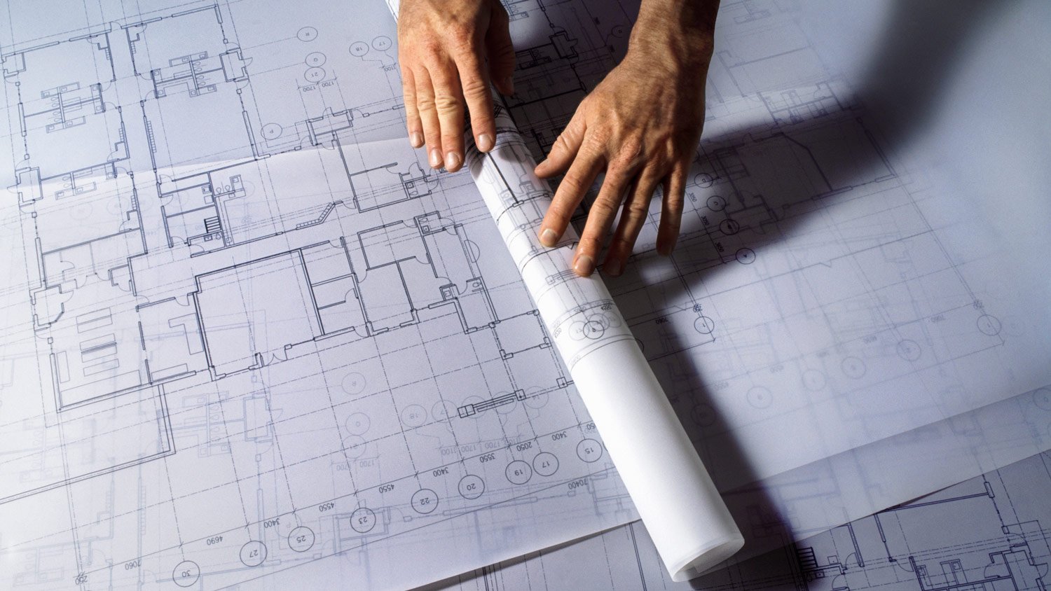
Blueprints are two-dimensional drawings of a three-dimensional building plan. They show everyone involved in the construction process (like construction workers, plumbers, and architects) how the building should be constructed. And since there are multiple moving parts in any construction project, each pro on the job will need different types of blueprints to finish the job as laid out in the drawing.

Understanding a blueprint the first time you look at it can feel overwhelming. Of course, you see the drawing itself, but what is everything else? We'll cover each part below so you’ll know how to read blueprints (and understand what’s going on).
The title block is on the bottom left of the first page of your blueprint. It contains information like its title, project overview, who drew the plan, who checked and approved it, its scale, and any necessary information to identify the project.
Revision blocks are generally located on the upper right of your title page or above your title box. At first, they’re blank and will only include information if there have been changes to the original blueprint. The information in this section would be the date, a description of the revision, and the revision number.
Blueprints are filled with abbreviations and symbols vital for a pro to understand so everyone working on the project is on the same page. That’s the purpose of a legend or key. It explains what each symbol is for, and what each abbreviation means.
Blueprints are mostly a collection of symbols, abbreviations, and lines. However, notes help explain the drawing in more detail to ensure professionals have all the necessary information. Different notes, such as keynotes and general notes, have distinct purposes, but the goal is to give more details for a drawing.
Ever wonder how pros can build homes or home additions to the correct size by reading a sheet of paper? That’s because it’s a scaled drawing, and each smaller measurement represents a much larger, realistic portion of the project. For example, every 1/4 of an inch on a blueprint will equal one foot. You can find a blueprint’s scale near its title.
Another standard part of a blueprint is its grid system. The grid is on your plans' horizontal and vertical edges, with letters on one edge and numbers on the other. This system helps quickly identify each part of a blueprint.
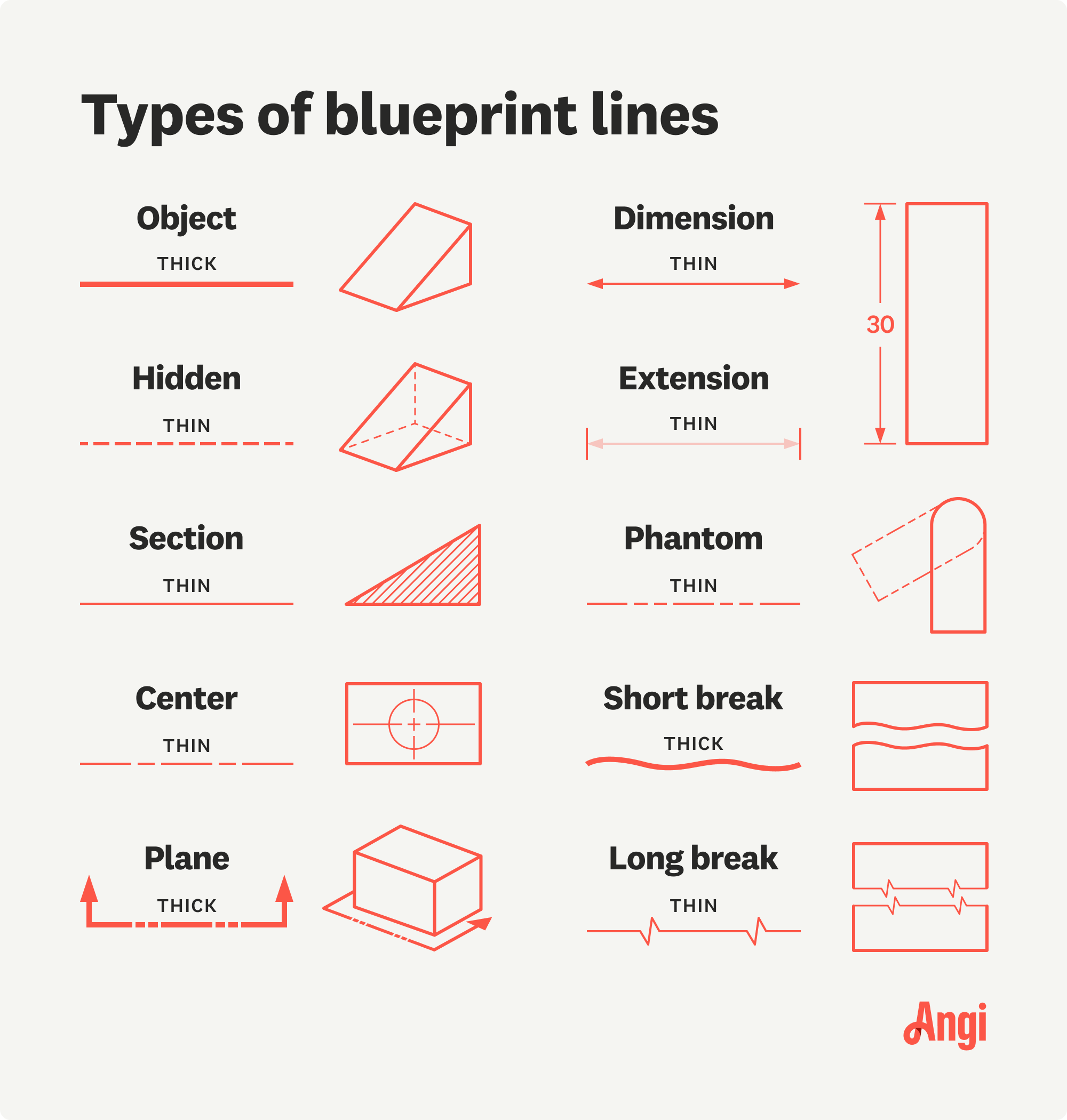
Besides the drawing, the lines are another part of a blueprint that’s hard to miss. It can seem like there’s no rhyme or reason for how the lines are used. However, there are different types of lines, each with its own purpose:
Object Line: The object line is a solid, thick line and is sometimes referred to as the visible line since it indicates the side of the line you can see when looking at it.
Hidden Line: These lines are the opposite of object lines, since they represent the hidden portion of an object and are referred to as invisible lines. Hidden lines are thin with short dashed lines.
Center Line: Center lines contain long and short dashes and are used to show the center of an object.
Dimension Line: These lines show the distance between objects and are thin lines with a number in the center and arrowheads on each end.
Extension Line: Extension lines are thin, short, and solid lines perpendicular to and located on each end of the dimension lines. They don’t touch the dimension lines but show where the distance ends.
Phantom Line: These lines show different positions an object can be in and are a thin line with a long dash and then two short dashes, repeating in that pattern.
Section Line: Section lines show the interior of an object in relation to the cutting plane line or cross-section view. These lines are often thin, parallel lines that run diagonally to the object.
Leader Line: These lines run at 45-degree angles with an arrowhead pointing to the object it’s describing and with numbers or words on the opposite end to describe that object.
Break Line: These lines show that a long object has been shortened to fit the drawing better. Short break lines are thick and curvy, while long ones combine solid, thin lines and zigzags.
Plane Line: Cutting plane lines give an interior view of an object. These lines go through the object, extending slightly past it, with short and long dashes and arrowheads on each end.


Not every blueprint is the same. Each sheet will contain different parts of the entire project. Let’s look at each sheet and what each one means.
A blueprint’s general sheet (G sheet) has all the essential information for the project on it. It’s typically the first sheet of your blueprint and has the plot plan, title and revision blocks, scale, and other tidbits of information that give a high-level view of your project.
Unlike the general sheet that focuses on the project as a whole, the architectural plans (A sheets) focus more on the design elements. If you want to know where the stairs and windows will go or any floor plan information, you’ll refer to the A sheets. Your local architect is typically the person to draw up these plans.
While your architectural plans are there to make a construction project look nice, your structural engineering plans (S sheets) ensure everything functions and is up to code. These plans detail the foundation, columns, beams, walls, etc. Their goal is to make sure the house is sturdy enough to hold its weight and not fall apart.
The MEP (mechanical, electrical, and plumbing) plans provide techs with everything they need to know to make a building livable. These plans are also known as the M, E, or P sheets in blueprints. The M sheets would include plans for the HVAC system. The E sheets will show the wiring system’s layout, while the P sheets outline the piping routes.
Not all construction plans include landscaping (L sheets). However, those that do outline the landscape’s layout. It helps landscapers see where each element goes, its distance from each other and the house, and the type of plants or walkways used.
Schedules aren’t plans. Their purpose is to describe the doors, windows, and finishes used throughout the blueprint. For instance, if you want to know what type of window will be used in your bathrooms, you can look through the window schedule to get a more detailed understanding of the window type and size.
You’re looking at a blueprint, and one page looks like a floor plan while another looks like a 3D image; what gives? Each blueprint view shows you a different perspective of your project. Let’s look at the most common blueprint viewpoints below.
An elevation view shows what a building will look like from its front, back, and sides. This view is what a building will look like from the outdoors. So, imagine driving up to your home; that’s what an elevation view on a blueprint will look like.
A section view allows you to see your building from the perspective of a vertically split building. It provides a similar view as a doll house and helps pros visualize elements and systems such as floors, HVAC, and walls in relationship to each other. These views help avoid potentially unseen structural and design issues.
A plan view on the blueprint for your home shows your home from above, looking down. It gives you a two-dimensional view and is mostly used when someone wants to show the entire home’s layout simultaneously. Buildings with multiple stores will have a plan view for each floor.
An isometric view provides a three-dimensional drawing of an object at an angle. It gives a more detailed perspective of how each element fits into the space. It also helps pros visualize how everything should look in an area.
Now that you know how to identify each element, how do you read a blueprint? Fortunately, understanding what you’re looking at is the first step of successfully reading a blueprint. Below, we’ll cover what steps you should take to read your blueprint.
First, look for your title and revision blocks to grasp what’s going on with your blueprint. Besides giving you an overall understanding of your blueprint, you’ll also find your scale here. The scale will help you see its relationship with your project’s size.
Next, identify the legend or key where the symbols and abbreviations will be located. You might only memorize some of them at first. But you’ll know what it means and where to look for more information when you run across new symbols.
Like the legend, your goal isn’t to memorize the notes but to have a good grasp on each one so you can match it with its corresponding section on the blueprint.
If you try to read your blueprint all at once, it can quickly get overwhelming. Instead, start with a small section of the blueprint and break it down. Look at it and see what you can quickly identify to help you get a better picture. Found thick, solid lines? Those are visible lines and the part of an object you’ll see when you walk into a room.
The objective is to learn how to read a blueprint, so it's best to start small, break it down into sections, and take your time.
If you’re struggling to read some or all of your blueprint, it never hurts to ask your pro for help. They can explain what each blueprint says, and how it relates to the overall project.
From average costs to expert advice, get all the answers you need to get your job done.

Wondering how much hiring an architect cost? Discover architect prices, cost factors, and money-saving tips to help you plan your home project with confidence.

Few things elevate your outdoor space like a landscape architect can. Learn about how much a landscape architect costs and what affects your total.

Get transparent draftsperson cost to hire info, including average prices, cost factors, and tips to help homeowners budget and save on drafting services.

Knowing whether to hire an architect vs. a contractor is important when building or remodeling. Learn the differences between the two.

Gothic-style architecture features distinctive design flourishes that give this style its dramatic, moody flair. Learn more about its key elements.

A drooping, damaged ceiling isn’t just an eyesore; it’s also a potential safety risk. Learn how to fix a sagging plaster ceiling in this step-by-step guide.