
What is a multimeter? Here's everything you need to know about this nifty device, which you should consider having in your toolbox for basic measurements and repairs.
Troubleshoot electrical problems to expand your DIY skills

Learning to use a voltmeter helps you troubleshoot electrical issues like dead batteries or faulty outlets, expanding your DIY skills for safer home repairs.
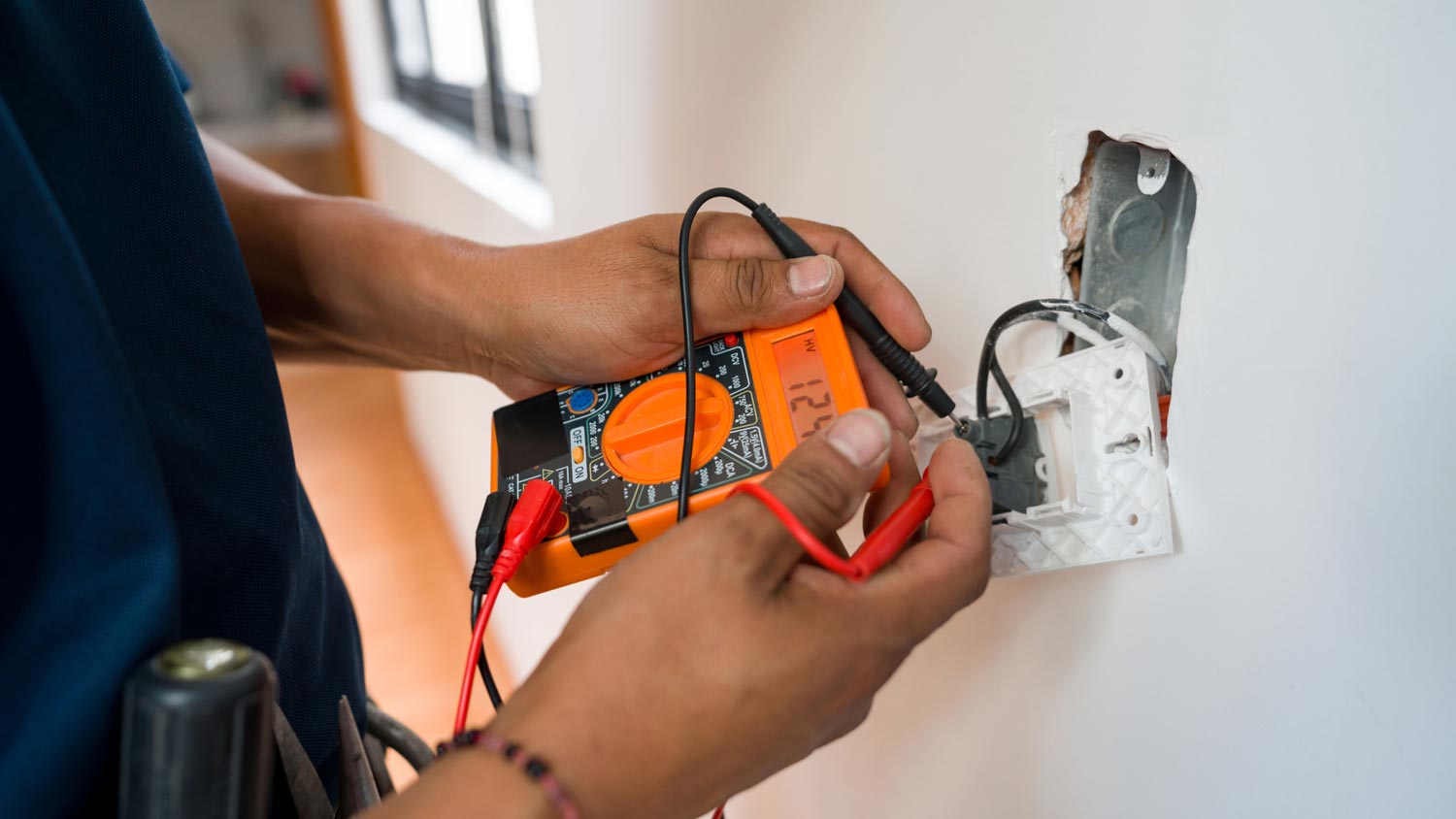
Measuring AC voltage with a multimeter reveals wiring problems in your outlets, and readings around 120 volts confirm your electrical system works correctly.
Testing DC voltage on batteries shows whether they hold enough charge, while checking continuity confirms your electrical connections and components have complete current paths.
Hiring a local electrical professional provides reliable guidance on multimeter readings and wiring diagnostics, keeping your home electrical work safe and accurate.
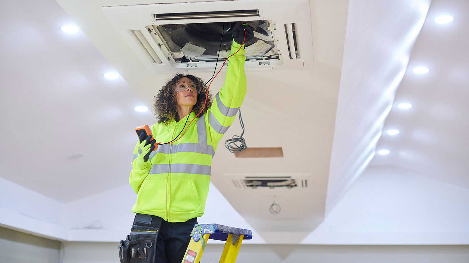
Need to check the life of a battery or diagnose a problem with outlet wiring in your home? Learning how to use a multimeter tester can help you solve these problems, which is why it’s a useful instrument to keep in your toolbox. You can use a multimeter tool to troubleshoot many types of issues, so use this guide to learn how to use a multimeter in various DIY scenarios.
A multimeter, sometimes referred to as a volt-ohm meter, is a versatile tool for homeowners to keep on hand that tests different units of electricity—voltage (AC and DC), current, and resistance.
Voltage: Measured in volts, alternating current (AC) and direct current (DC) are two forms of voltage that a multimeter can test. AC is the flow of an electrical current that changes directions, usually found in the electrical wiring throughout your home. DC is the flow of an electrical charge in one direction, normally used in batteries, vehicles, and other electronics.
Current: Current is measured in amps or amperage, and a multimeter tests the strength of a current to determine the amount of electricity flowing through a circuit. It’s an important safety measure to test the current amount when you’re doing an electrical project, such as wiring a light switch, to ensure the electricity is completely off.
Resistance: Measuring resistance determines the opposite flow of electricity, using ohms as the unit of measurement. Resistors are most commonly used in household appliances and electrical devices.
Continuity: Continuity tests measures for a complete path of current. All circuits need a continuous path for electricity to flow through. For example, if an appliance fails, it could be because there’s an open circuit, meaning it’s devoid of continuity. Replacing the component could fix the appliance, allowing it to work properly again.
There are digital multimeters and analog multimeters that perform the same function but have a different display. A digital multimeter features an LCD display, whereas an analog multimeter has a needle that moves over a numerical scale.
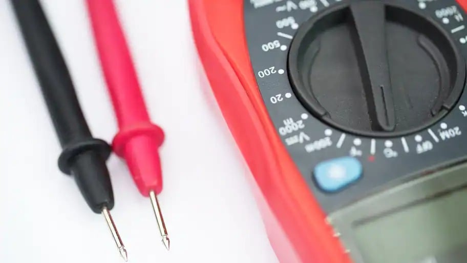
Let’s review the different parts of a multimeter. Remember, the features can differ from model to model, so your multimeter may not have the same options as the ones listed.
Display: The display is the LCD screen (digital) or scale (analog) that depicts the reading of the electrical measurement.
Selection knob or button: This is the knob or button that allows you to switch between different units of measurement. Here are some of the abbreviations that you may see on your multimeter:
AC volts (V with a wavy line over it)
DC volts (V with three hyphens and a straight line on top)
Resistance (ohms or Ω)
Amps (A)
Milliamps (mA)
Continuity (diode symbol or a soundwave symbol)
Hold button: The hold button is used to keep track of a certain reading, so you don’t need to write it down to recall the measurement at a later time.
Test probes: On a multimeter, two probes (also referred to as test leads) are plugged into the ports with a pronged banana jack to test the electrical component. On the other end of the probe is a metal tip—sometimes referred to as the terminal. The red probe tests for a live current, and the black probe tests ground or neutral terminals.
Ports: Most multimeters have two or three ports to connect the leads. All multimeters will have a black common port labeled as COM for common. This is where the black probe plugs in. The mAVΩ port is the port that the red probe plugs into and is used to test most electrical measurements, such as volts, resistance, and current. The mAVΩ port may also be labeled as VΩ or V. Your multimeter may also have a red 10A port, but it is used less often than the mAVΩ port and typically tests large currents (up to 10 amps).
Note: It’s important to learn the difference between a multimeter and a voltmeter. A multimeter and a voltmeter are different electrical measuring tools with one thing in common: They each measure potential voltage. The difference between the tools is that voltage is the only measurement a voltmeter can determine.
Now that you understand the basic uses and components of a multimeter, it’s important to take adequate safety measures when performing electrical work.
Inspect the multimeter for any signs of damage, such as cracks, dings, or leaks, to ensure a safe and accurate reading.
Wear insulated gloves and rubber shoes to add a layer of protection when performing electrical tests.
Don’t test any wires that are damaged or frayed.
Only perform electrical testing in dry conditions.
Never touch the metal tips of the probes with your hands.
Ensure the multimeter probes are working properly internally by “ohming-out” the leads. Put the multimeter in the resistance (ohms or Ω) setting, then connect the probes to the port (plug the black probe into the COM or common port and plug the red probe into the red mAVΩ port). Touch the tips of the probe together (making sure not to touch the tips with your hands), and check that the reading is 0.5 ohms or less. If the reading is over 0.5 ohms, you will need to replace the probes.
Always keep the multimeter in its case when not in use.
Follow this guide to learn how to use a multimeter to measure AC or DC voltage, resistance, and continuity.

Measuring AC voltage is one of the most common uses for a multimeter, and can read a standard three-prong wall outlet to identify any potential wiring problems.
To measure the AC voltage, turn the selection knob to AC volts (typically marked V~, VAC, or ACV), beginning at the higher range and adjusting down as you progress.
If you’re testing an outlet, start by turning off the power to the plug from the circuit breaker.
Then, connect the black probe to the common jack, and plug the red probe into the AC voltage port on the multimeter.
Identify the outlet you’re testing and look for the wide and narrow slot. On a polarized plug, the wider prong is neutral and the thinner probe is the live or hot prong.
Put the black probe (or the negative terminal) into the neutral prong and the red probe (or the positive terminal) into the hot prong.
Check the reading on the display of the multimeter. The measurement should read around 120 volts, and if not, there’s likely a wiring issue.
Once you have the reading, remove the red probe first, then remove the black probe.
Unplug the test probes from the ports on the multimeter in the same order—red first, then black.
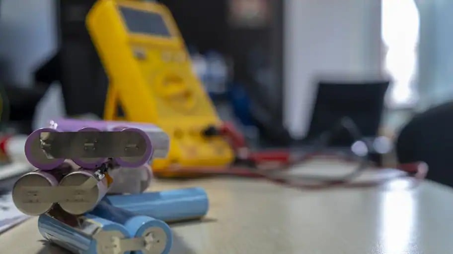
Measuring the DC voltage can be used to read batteries—including a car battery. Remember, if you’re testing a car battery, turn the headlights on for two minutes, then turn them off to drain the battery enough to determine whether or not there is enough voltage left to power the vehicle efficiently.
Disconnect the battery from the power supply.
Switch the selection knob to the DC voltage setting (typically marked V–, V---, VDC, or DCV) at the expected measurement on the multimeter, which can be determined by looking at the manufacturer’s label. For example, an AA or AAA battery will have a voltage indicator on the side of the label indicating 1.5V.
Touch the black probe to the battery’s negative side, and touch the red probe to the positive side.
Read the measurement on the display.
Remove the red probe first, then the black from the battery. Then, remove the jacks from the multimeter in the same order—red then black.
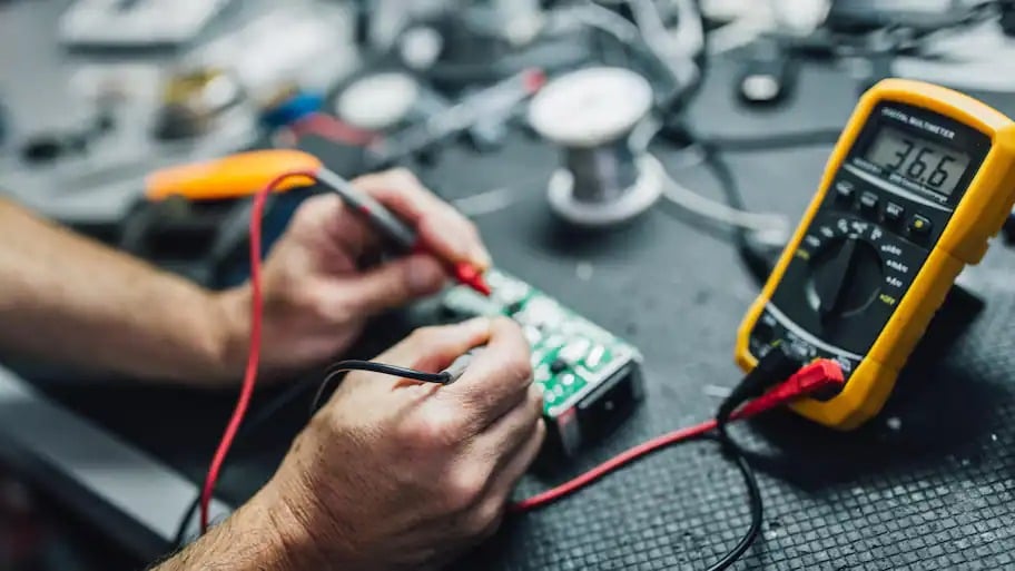
Measuring resistance can check an electrical component’s resistor and determine if repairs are necessary.
Disconnect the device or component from any source of electricity, such as circuits, plugs, or batteries, so there isn’t a flow of current.
Check the resistance value of the resistor based on the manufacturer’s guidelines or the label of the component.
Switch the selection knob to the ohms (Ω) setting at the expected resistance level on the scale.
Plug the black probe into the COM jack, and plug the red probe into the mAVΩ port.
Touch the red and black terminals to the sides of the component you’re testing. It’s important to note that positive and negative doesn’t matter when you’re testing resistance.
Read the measurement on the display. Remember, the test probes carry about 2 ohms of resistance, so you can subtract two from the reading to determine the final measurement.
If the reading on the multimeter matches the suggested resistance value, the resistor is in good condition. Otherwise, you’ll need to replace it.
Depending on the multimeter, there may be a continuity setting. Continuity testing allows you to determine if there is a complete path of current flow in a switch, electrical connection, fuse, or conductor. Moreover, you can use check continuity to determine whether a power cord is functional.
Set the selection knob to the continuity setting.
Plug the black probe into the COM port and the red probe into the mAVΩ port.
Touch the tips of the red and black terminals together, and look for a number that is zero or close to zero on the display. That reading indicates there is continuity.
Place one terminal on one side of the electrical component you’re testing, and place the other terminal on the other end of the component. If the number is zero or close to zero, there’s continuity.
If there’s no continuity, the multimeter will display “OL” or “open loop.” This reading indicates that you need to replace that component.
A voltmeter measures the potential difference between two points in a circuit to determine the voltage. This method can be useful when diagnosing an issue with an electrical outlet or testing a battery.
Select DC or AC on the voltmeter knob. Choose DC if you are testing small electronics or batteries and AC if you are testing electrical outlets. If your voltmeter doesn’t explicitly show a DC or AC selection, DC may be represented by a straight line and AC by a wavy line.
Spin the voltmeter knob to a voltage range that is one setting higher than the voltage you want to measure to choose the upper limit of the measurement. To determine this value, check the label on the electronic. For example, standard household outlets are 120 volts, so set the voltmeter to 200 volts.
Grab the black and red probes, also called needles, on the voltmeter and turn on the voltmeter. Touch the end of the black and red probes together. The voltmeter should read zero. If it does not, your voltmeter is not working properly and you should repair or replace it.
With the voltmeter still on, place the red probe in the positive connection of your battery, device, or outlet and the black probe in the negative one. The positive and negative ends of a battery are marked with “+” and “-” symbols. If measuring the voltage of an outlet, it does not matter which probe you place into each rectangular hole of the outlet (avoid the round ground hole).
With the probes in place, read the number displayed on your voltmeter—this is your voltage reading.
Great company! Price was competitive, technician showed up on time and completed the job (exterior electric Radon fan replacement) quickly. Would hire them again.
I conferred with 2 other contractors before Armstrong Electric. Nick and his crew showed me that the project was not as convoluted as the other contractors made it appear to be. They completed the entire project on time. They were professional, friendly and cleaned up after at completion. I...
 Armstrong Electric LLC
The techs on my project, Shawn and Cliff, were great. They were prompt, courteous, and efficient. I am very happy with the results and would definitely contact Mr. Electric for any future electrical projects.
Victor was wonderful. He was on time, professional, and explained everything he was doing. He was thorough and figured out that the problem was electrical instead of with my HVAC system. Very knowledgeable. I will be using this company in the future for any HVAC needs. Thanks!
 Hubbs Heating & Air LLC
They were excellent. They did a great job. I was totally satisfied. They put tremendous effort in making sure the work was completed. They were great. They provided immediate response to any inquires I made. I would hire them again. I would recommend them to anyone who needs electrical work....
 Property-Tech Industries, LLC
Initially, the repairman could not find the problem. Apparently, there was some electrical shortage, but he could not find the definite problem. He left, but called back later to say he had a new idea. He returned and replaced the light switches on the doors. The refrigerator seemed to return...
 Appliance Pro LLC
The initial quoted price from a walk-through seemed high, but we discussed that the quote represented worst case scenario (re-wiring to two floors) and we were excited about the opportunity to have the work done in a timely manner with closing for fire safety reasons, etc. When the job was...
I have to tell you I am all about customer service - I will go out of my way and even pay more for it if you give me great customer service. <br> <br>In a world where this is hard to find, these guys were awesome! I can not sing their praises enough. They were prompt, personable, funny, got...
 Waibel Electric
When I challenged the markup on the generator, Bruder Electric withdrew its bid. They only want naïve customers.
We had no power to any of the electrical outlets in the MBR. We'd had an intermittent problem for a few years and they finally went out all together. We live on the 3rd floor of a 100 year old building and I know from past experience the wiring has been added to in hodgepodge ways over the...
From average costs to expert advice, get all the answers you need to get your job done.
What is a multimeter? Here's everything you need to know about this nifty device, which you should consider having in your toolbox for basic measurements and repairs.
Voltmeters and multimeters have similar functions, but also key differences that impact which one is right for you.
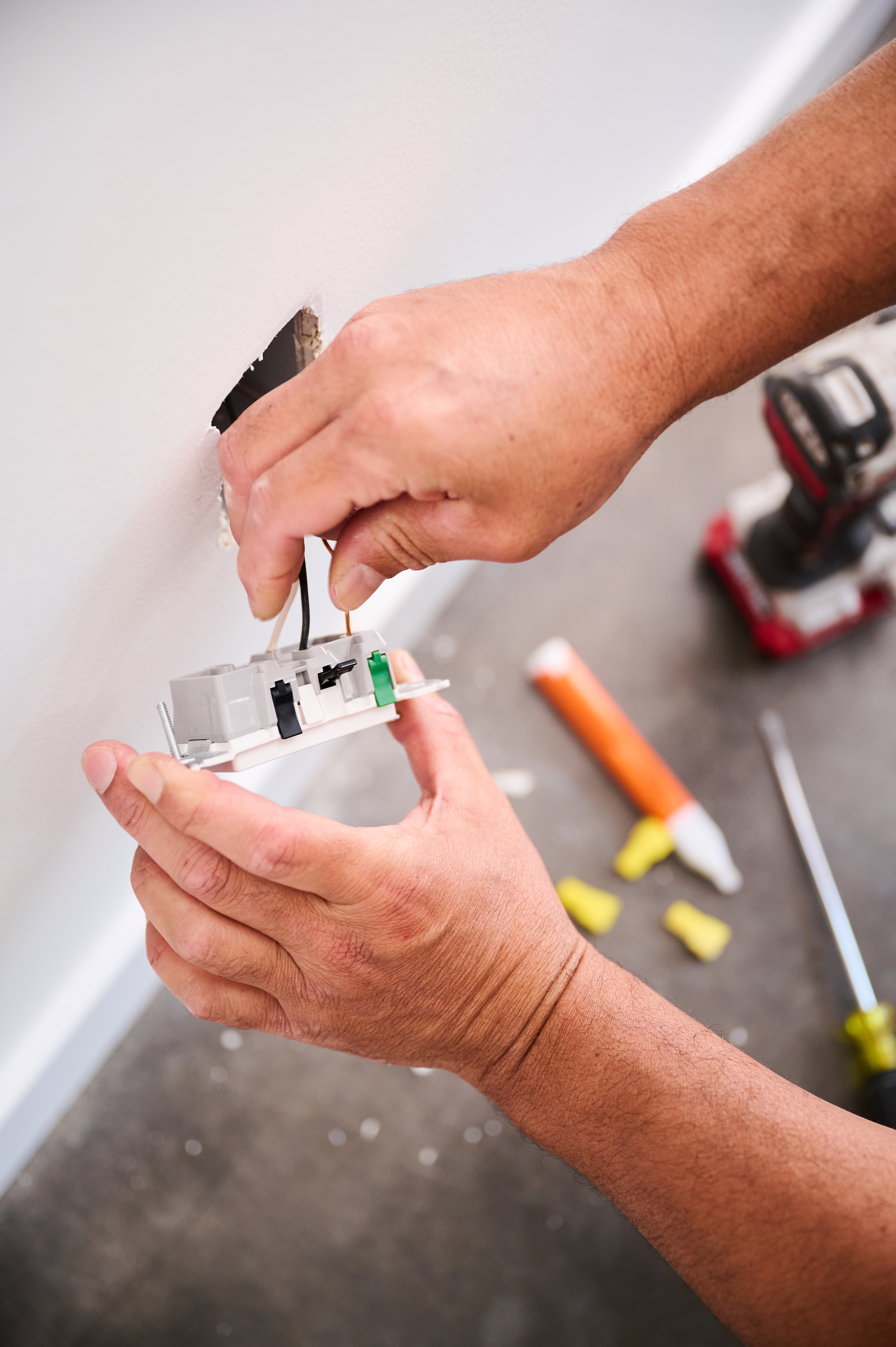
Do you know if the black wire is positive or negative? If not, stop right now and check out our guide on differentiating electrical wires.

When it comes to precise measurements, you need a precise tool. A micrometer can definitely come in handy, so learn how to read a micrometer here.
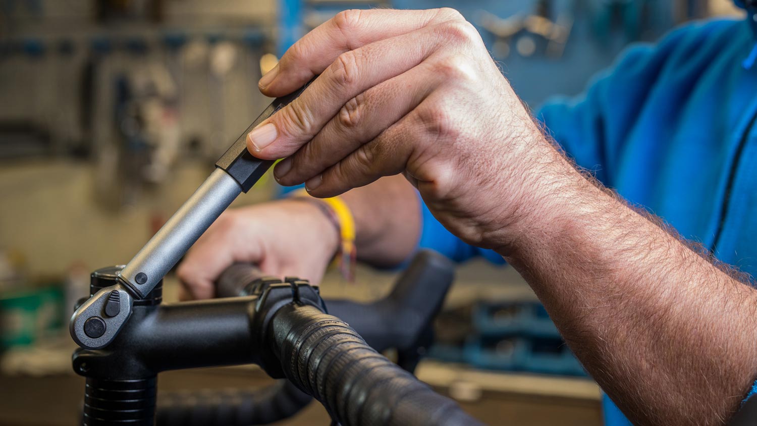
You're working on some DIY projects and the instructions call for a torque wrench. Read this guide to learn how to use a torque wrench like a pro.

Learn how to test Christmas lights quickly and easily, no matter what kind of light strands you have to keep the Holidays bright and cheery.